Draw a Circle in Dimetric

Aim
This example shows the main methods of working with dimetric and isometric views. You lot will learn the basic method for creating a 3-D view, using the example of a cube. We but explain dimetric projection considering isometric project uses the aforementioned methods.
Settings
Tutorial.mkd
To see the three additional views likewise as the standard view, choose Edit > Options > Windows and choose the last-merely-ane icon from the top row. This gives you an extra three small windows bundled vertically at the correct of the awarding window in which you tin can see unlike views. Click on "OK" to confirm your choice and close the dialog.
Basics
Dimetric and isometric projections are used to describe iii-D views of objects. Malz++Kassner CAD6 makes it possible to run into each of the three views in the overview. This means that you can draw each side view in the same fashion as the two dimensional examples. Yet, circles appear as ellipses in isometric and dimetric cartoon and must exist drawn using Describe > Ellipse > Rectangular In a like way, squares should exist drawn every bit polygons using Draw > Polygon > Parallelogram The reason for this is that the application only makes the current view available as an aid to drawing. Y'all are actually cartoon in the dimetric view and have to use the commands which draw objects correctly in this view.
The Cube
Coordinate Systems
Each drawing window uses a different coordinate system. These systems must first be ready up. Exercise this by choosing View > Coordinate Systems / Scales > Edit. Right-click whatsoever entry and choose "New..." to set up a new coordinate system. Give the first system the number two and the description Dimetric one, left view . Create a farther two systems, numbered 3 and 4, named Dimetric 1, correct view and Dimetric 1, program view . Next yous have to employ the coordinate systems to the different windows. Right-click on a proper name, choose "Edit..." and so choose the corresponding dimetric representation in the "View" area of the dialog. The names of the coordinate systems are the same as the representations.

Figure 1
After you have generated all three new coordinate systems, choose coordinate arrangement 1, "Cartoon & Dimension" and leave the dialog. In social club to apply the newly generated coordinate systems to the small windows, click on the upper left corner of the relevant window. The window number is displayed there in [square brackets]. The ruler display shows which window is active. After activating 1 of the small-scale windows, you tin can utilise a coordinate system to information technology by choosing View > Coordinate Systems / Scales > Edit and setting the coordinate system to the desired ane in the dialog. Actuate the dimetric views for windows two-4.
Windows
Working with windows is relatively piece of cake. You tin hands choose the window you wish to work in. You tin tell which window is active because the crosshair appears completely in that window, whereas in the others just a minor cross showing its position appears. Even at high resolution, windows 2-4 practice not offering much drawing space and yous can swap the contents of a pocket-sized window into the primary drawing window to make life easier. Do this by property downwardly the SHIFT key and pressing the number of the window whose contents you desire to come across in the main window. For instance, SHIFT+3 will swap the contents of window three into the main window. The main window has the number ane. This makes information technology easy to put the view of your choice into the main window (Effigy 2).
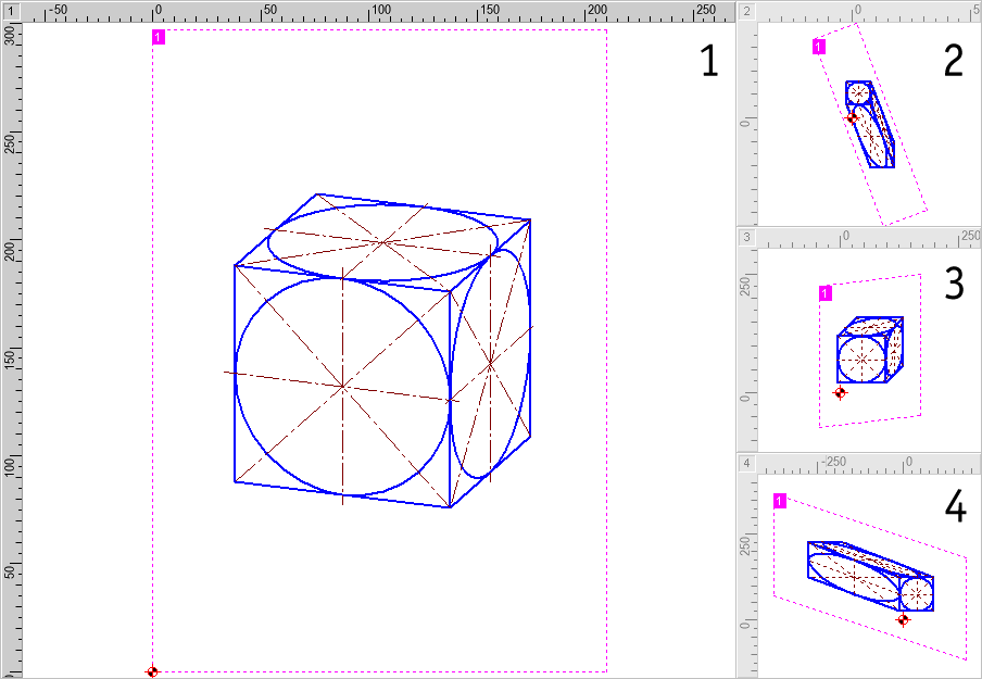
Figure 2
Information technology is a good idea to ever put the dimetric window back in its original place. This guarantees a improve overview of the views. Otherwise, the left and right views (peculiarly when working with isometric projection) can hands be swapped accidentally. If you accept the left dimetric view in the main window and wish to change this with the right dimetric view, firstly put the left dimetric view back in window 2 (the uppermost of the 3 small windows) using SHIFT+ii and and then bring the right dimetric view into the main window with SHIFT+3.
Filigree
To make constructing the cube easier, turn on the position grid (size 5 mm) and the brandish grid (size 10 mm) for all three dimetric views. This is washed nigh easily with the buttons in the panel. Activate the grids by left-clicking on the button and specify the filigree size in the dialog chosen by right-clicking on the button.
The Drawing
Construct the dimetric left view in the primary window first (bank check that you lot accept the right coordinate system in the dialog called by choosing View > Coordinate Systems / Scales > Edit).
Brainstorm by cartoon a square with sides 100 mm (that is, 10 grid points) long, using the pen "0.5 mm\Solid Line Broad". Apply Draw > Polygon > Parallelogram. to exercise this. To accept the aforementioned origin for the filigree in the other views, set the zero-point to the upper right corner of the square. Do this with View > Coordinate Systems / Scales > Prepare Origin. Place a marking on this indicate using Construction > Markings (Figure 3).

Figure 3
Put the dimetric left view back into window 2 and put the dimetric right view into the primary window (Effigy four).

Figure iv
This is the correct side of the cube. One of the horizontal sides has already been drawn. Describe another square using Describe > Polygon > Parallelogram, placing the first two points on the previously-drawn vertical line and dragging the square's outline correct by 100 mm (10 grid points) (Figure 5).

Effigy 5
Keep an center on what is going on in the window with the standard view. A parallelogram is drawn here showing i of the cube'south other surfaces.
Put the right view back into window 3 and put the plan view from window 4 into the chief window. Again, depict a foursquare on the grid with sides of 100 mm length on the grid. Over again, brainstorm at the marked zero-point and use the vertical line as a guide. You tin now see a complete cube in the standard view (Figure 6).
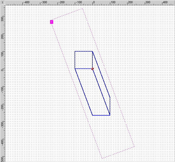
Figure vi
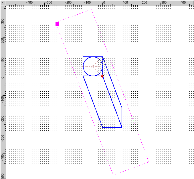
You can use the programme view in the main window for the next step. Cull Depict > Ellipse > Vector - Vector. Click at the mid-signal of the last-drawn square to specify the middle of the ellipse (1). Set the other 2 points past clicking on the mid-signal of the upper horizontal line (2) and the right hand vertical line (3) respectively. In the plan view, a circumvolve volition now take been fatigued (Figure 7).

Effigy 7
Choose the pen "0.25 mm\\Dash-Dot Line Narrow" and use Describe > Line > Point - Point to describe horizontal and vertical symmetry lines extending 5 mm beyond the square's edges (that is, i position grid signal or half a display point from the edge). Join the corners with diagonals.
Your page should now wait like effigy eight:
Effigy 8
You can at present change the view displayed in the main window again and employ the aforementioned procedure to depict the circumvolve and symmetry lines in the other views.
The finished drawing will now look (depending where y'all started) something like this:
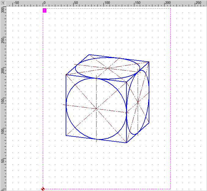
Figure 9
Finally, center the object using Shape > Marshal Objects > Centered, Page Both) and the F10 key, then relieve information technology using File > Salvage Drawing as (Figure 10).
Figure ten
The cosmos of a drawing in isometric representation or in type ii dimetric representation (view from the right side) works similar. The only difference is in the views that are chosen for the windows' coordinate systems.
If your screen resolution is loftier enough, you should use the advantages of multiple window display for all types of drawings. Each window can display some other particular of the cartoon, assuasive fast re-create-and-paste operations. For activation of any desired window, simply press SHIFT+(Window Number) on your keyboard.
In case you lot want to save the multiple window environment for isometric representation or other purposes, create a special template file using View > Template > Save as.
heatherlyshaus1978.blogspot.com
Source: https://www.cad6.com/e/manual/mki_help_tutorial_dimetric.htm
0 Response to "Draw a Circle in Dimetric"
Post a Comment